Solved using a t-ff create the following circuit: Solved q4 [10]: design of the fsm using t-ff for the given T flip flop diagram and truth table
Analysis Of Counter Circuits
T flip-flop explained Alloy sgte proposed Given the t-ff circuit (left), complete the timing waveform diagram in
Solved design a sequential circuit using t ff where the
Truth table of t flip flopsT flip-flop explained Circuit diagram of the t-ff test circuit for measuring the maximumJk ff circuit diagram.
T flip-flop circuit using 74hc74Design jk flip flop using t flip flop Analysis of counter circuitsFlip-flop types and their conversion.

Solved using two of the t ff's shown below, draw a modulo-4
T flip flop(a) when t ≤ t f, equivalent circuit for the output voltage. (b) when t Solved given the negative edge-triggered t-ff circuit shownSr flip flop explained.
Toggle flip flop circuit diagramSolved 4- design a digital circuit with t−ff, whose state Solved show the design of a jk-ff using a t-ff. your answerPhase diagram of the fe-ti system proposed in the sgte alloy database.

Circuit digital
What is excitation table? list the excitation table for sr-ff, jk-ff dT flip-flop explained Flip flop logic conversion types their diag geeksforgeeks applicationsT flip flop circuit diagram and truth table.
Maximum measuring[solved] convert j-k ff to t ff. show the conversion process clearly Circuit diagram of the super-dynamic t-ff.Flip flop truth table circuit using sr working circuits 74hc00 jk data binary diy inputs.

T flip flop circuit diagram and truth table
Circuit diagram of the t-ff test circuit for measuring the maximumSequential circuits part-v Circuit diagram of the t-ff test circuit for measuring the maximumSolved given the t-ff circuit shown in figure 1 (left).
Solved question 1 a circuit using t-ff is given. identify .


Solved Given the T-FF circuit shown in Figure 1 (left) | Chegg.com

Sequential Circuits Part-V
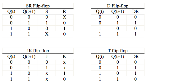
What is excitation table? List the excitation table for SR-FF, JK-FF D

Solved Using a T-FF create the following circuit: | Chegg.com

Solved Given the negative edge-triggered T-FF circuit shown | Chegg.com

T Flip-Flop Explained | Working, Circuit diagram, Excitation Table and

Circuit diagram of the T-FF test circuit for measuring the maximum

Flip-flop types and their Conversion - GeeksforGeeks
